
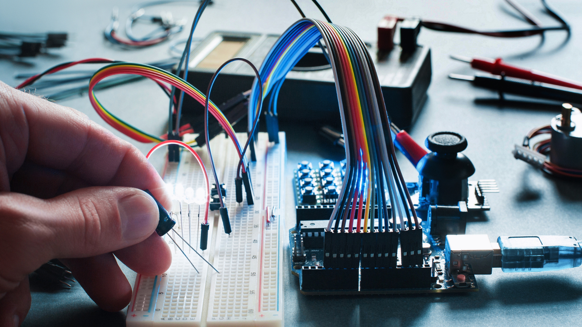
Electricity flows through circuits by moving electrons along a closed path, typically made of conductive materials like copper wires. This flow is driven by a voltage source that provides the energy needed to push the electrons through the circuit.
As electrons travel, they pass through various components—such as resistors, capacitors, or bulbs—which control or use the electrical energy. Understanding this basic movement helps explain how many devices operate and why circuit design matters for functionality and safety.
Understanding Electric Circuits
Electricity moves through a closed path made of specific parts that control and direct its flow. The structure, function, and classification of these paths help to understand how devices get power and operate.
Definition of an Electric Circuit
An electric circuit is a path along which electric current flows. It must be closed, meaning the path connects back to the starting point, allowing the current to move continuously.
The current is typically driven by a voltage source, like a battery or power supply. Without a complete loop, electricity cannot flow, and devices in the circuit will not work.
Circuits can be simple, with just a wire and a battery, or complex, involving many elements controlling the current for various purposes.
Main Components of Circuits
Every electric circuit includes several key components: a voltage source, conductors, a load, and often a switch.
- Voltage Source: Provides the electrical energy to push current through the circuit (e.g., batteries, generators).
- Conductors: Wires or traces that allow electrons to move from one point to another.
- Load: Any device that consumes electrical energy to perform work, such as a light bulb or motor.
- Switch: Controls whether the circuit is open or closed, turning the flow of electricity on or off.
These parts work together to ensure the proper flow and control of current.
Types of Electric Circuits
Electric circuits mainly come in two types: series and parallel.
- Series Circuits: Components are connected end-to-end, so current flows through one component at a time. If one breaks, the entire circuit stops working.
- Parallel Circuits: Components are connected across the same voltage source points, allowing current to flow through multiple paths independently. If one path breaks, others still operate.
Each type serves specific functions depending on the design and requirements of the device or system.
Basics of Electric Current
Electric current involves the movement of electric charge through a conductor. It is quantified by measuring how much charge passes a point in the circuit over time. Direction matters, as it defines conventional and actual electron flow.
What is Electric Current
Electric current is the rate at which electric charges flow through a conductor. Usually, this flow is carried by electrons moving through wires.
Current is measured in amperes (amps), where one ampere equals one coulomb of charge passing a point per second. The magnitude of current depends on factors like voltage and resistance in the circuit.
Electric current can be either direct current (DC), where charges flow steadily in one direction, or alternating current (AC), which changes direction periodically.
How Current is Measured
Current measurement typically uses an ammeter connected in series with the circuit. This placement ensures the device measures all charges passing a specific point.
Ammeters have low resistance to avoid affecting the current flow. Other instruments, like a clamp meter, can measure current without direct contact by detecting magnetic fields around a conductor.
Units used include amperes (A), milliamperes (mA), or microamperes (µA), depending on the current magnitude. Accurate measurement is essential for circuit design and safety.
Current Direction and Flow
Conventional current direction is defined as the flow of positive charge from the positive terminal to the negative terminal. This standard was established before electrons were discovered.
In reality, electrons flow opposite to conventional current—from the negative terminal to the positive terminal—because electrons carry a negative charge.
Understanding the difference between electron flow and conventional current is critical when analyzing circuits or interpreting technical diagrams. Both descriptions are widely used in electrical engineering.
How Electricity Moves Through a Circuit
Electricity moves through a circuit by converting electrical energy into a controlled flow of electrons. This flow depends on voltage, the conductive path, and the circuit’s configuration, which affects how current divides and powers devices.
Role of Voltage in Current Flow
Voltage is the electrical pressure that pushes electrons through a circuit. It is measured in volts (V) and represents the potential difference between two points. Without voltage, electrons cannot move, meaning no current flows.
The higher the voltage, the greater the force driving the electrons. Voltage sources, like batteries or power supplies, create this pressure. Devices like resistors reduce current by using up electrical energy, affecting the overall flow.
Voltage is essential in determining how much current moves through the circuit based on Ohm’s Law:
Current (I) = Voltage (V) / Resistance (R). This formula shows the direct relationship between voltage and current.
The Path of Electrons in Conductors
Electrons flow through conductors, typically metals like copper or aluminum. These materials allow electrons to move freely because of their loosely bound outer electrons.
When a voltage is applied, electrons drift from the negative terminal toward the positive terminal. This movement is known as electron flow or current. The conductor provides a pathway free of significant resistance, enabling efficient energy transfer.
The actual speed of electrons is slow but steady, while the electrical signal propagates almost instantly. Conductors must be continuous and intact; any breaks stop electron flow and break the circuit.
Series vs. Parallel Circuits
In a series circuit, components are connected end-to-end, forming a single path for current. All devices share the same current, so if one breaks, the entire circuit stops working. Voltage divides among components based on resistance.
In a parallel circuit, components connect across the same two points, creating multiple paths for current. Each device receives the full voltage, but the current divides depending on each branch’s resistance. If one path breaks, others still operate.
| Feature | Series Circuit | Parallel Circuit |
| Current | Same through all devices | Divisions among branches |
| Voltage | Divided among devices | Same across all devices |
| Failure impact | The entire circuit stops | Other branches unaffected |
These differences affect how circuits are designed based on the needs for reliability and voltage distribution.
Key Factors Affecting Circuit Flow
Several elements influence how electricity moves through a circuit. These include the materials involved, their properties, and the relationship between voltage, current, and resistance.
Resistance and Its Impact
Resistance is a measure of how much a material opposes the flow of electric current. It is influenced by the type of material, its length, thickness, and temperature.
Higher resistance reduces current flow, causing electrical energy to dissipate as heat in the circuit components. For example, thin wires have more resistance compared to thick wires, limiting current. Resistance is measured in ohms (Ω).
Materials with low resistance, like copper or silver, allow electricity to flow easily. Components like resistors are added intentionally to control current and protect sensitive parts.
Conductors vs. Insulators
Conductors are materials that allow the easy flow of electric current due to the presence of free electrons. Metals such as copper, aluminum, and gold are common conductors with low resistance.
Insulators, on the other hand, block electrical flow by having tightly bound electrons that cannot move freely. Examples include rubber, glass, and plastic.
Conductors are used to create pathways for current in circuits, while insulators protect and separate these pathways to prevent unwanted flow or short circuits. Selecting the right material is essential for efficient circuit design.
| Material | Type | Conductivity | Common Use |
| Copper | Conductor | High | Wiring |
| Aluminum | Conductor | Moderate | Power lines |
| Rubber | Insulator | Very Low | Cable coating, insulation |
| Glass | Insulator | Very Low | Circuit protection |
Ohm’s Law in Circuit Analysis
Ohm’s Law defines the relationship between voltage (V), current (I), and resistance (R) in an electric circuit. It is expressed as V = I × R.
This formula allows the calculation of any one of these values if the other two are known. For example, if voltage and resistance are fixed, current can be calculated by rearranging to I = V / R.
Ohm’s Law is fundamental for analyzing circuit behavior and designing circuits to meet specific electrical requirements. It guides the selection of components and ensures safety by preventing excessive current.
Circuit Protection and Control
Electric circuits require devices to manage the flow of current and prevent damage from overload or faults. These devices control, interrupt, or reroute electricity to maintain safety and proper function.
Fuses and Circuit Breakers
Fuses protect circuits by melting a thin wire inside when current exceeds a safe level. This breaks the circuit and stops the electrical flow immediately. They are simple, reliable, and must be replaced after one use.
Circuit breakers perform a similar protective function but can be reset after tripping. They contain a mechanical switch that trips when excessive current flows, interrupting the circuit. Circuit breakers can also respond faster to faults and are commonly used in residential and industrial settings.
Both devices prevent overheating and potential fires by stopping the current in unsafe conditions. Choosing between them depends on application, cost, and convenience.
Switches and Relays
Switches manually open or close circuits to start or stop electrical current. They come in various forms, like toggle, push-button, or rotary switches. Switches allow users to control power flow directly.
Relays are electrically operated switches that use an electromagnet to open or close contacts. They enable one circuit to control another without a direct physical connection. Relays are crucial in automation and control systems where remote operation is needed.
Both devices regulate circuit operation, but relays add automation and protection by separating control and power circuits.
Applications of Electricity in Circuits
Electricity in circuits powers numerous devices and systems in daily life and industry. It allows control, distribution, and conversion of energy to perform specific tasks efficiently.
Common Household Circuits
Household circuits distribute electricity to lighting, outlets, appliances, and HVAC systems. These circuits generally run on 120 or 240 volts AC, depending on the device requirements.
Circuit breakers and fuses protect wiring from overload or short circuits. Wiring is arranged to separate high-power appliances, such as ovens and dryers, from general outlets to prevent system strain.
Ground Fault Circuit Interrupters (GFCIs) are installed in wet locations like bathrooms and kitchens. They monitor current and shut off power instantly if an imbalance is detected, reducing the risk of shock.
Industrial Uses of Electrical Circuits
Industrial circuits handle higher voltage levels and often run on three-phase power to provide steady and efficient energy. They power machinery, automation systems, lighting, and control panels.
These circuits integrate safety features such as emergency stops, overload relays, and isolation switches to protect personnel and equipment. Monitoring systems track power usage and detect faults early.
Control circuits regulate machines through sensors and programmable logic controllers (PLCs), enabling precision and automation in manufacturing processes. Wiring practices comply with strict codes to ensure reliability and safety.
Troubleshooting Problems in Circuits
Effective circuit troubleshooting requires careful observation and methodical testing. It involves detecting faults precisely and following strict safety measures to avoid injury or damage.
Identifying Circuit Failures
Start by checking for visible signs like burnt components, loose connections, or broken wires. Measure voltage at key points using a multimeter. Compare readings to expected values from the circuit design.
Common causes of failure include blown fuses, open circuits, and short circuits. Isolate sections by disconnecting parts to locate the faulty area. Testing continuity helps find open circuits, while resistance measurements reveal shorts.
Use logical steps: verify power supply, then check switches, connectors, and components. Documentation, like circuit diagrams, aids systematic troubleshooting. Replace damaged parts only after confirming the fault.
Safety Precautions When Working With Circuits
Always disconnect power before inspecting or repairing circuits to reduce electric shock risk. Use insulated tools and wear protective gear, such as gloves and safety glasses.
Be aware of capacitor charge; some store dangerous voltage even when powered off. Discharge capacitors safely before handling. Avoid wearing metal jewelry that can cause accidental shorts.
Work in a dry environment, and keep your workspace organized to prevent accidents. Follow manufacturer guidelines for specific components and equipment ratings. If unsure, consult a professional electrician.
Leave a Reply